
Search
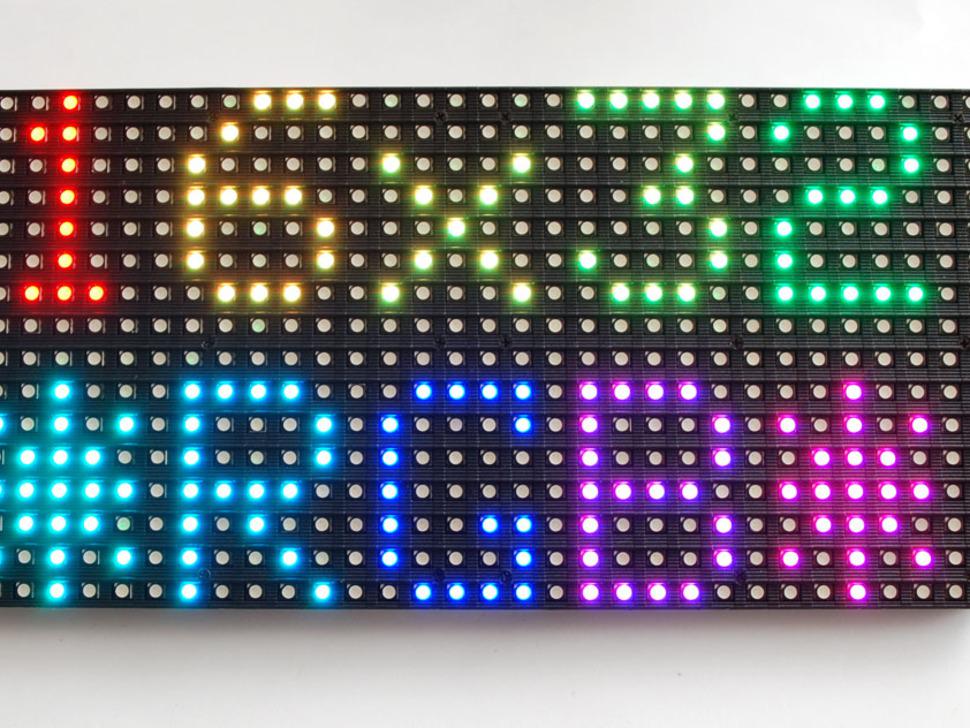
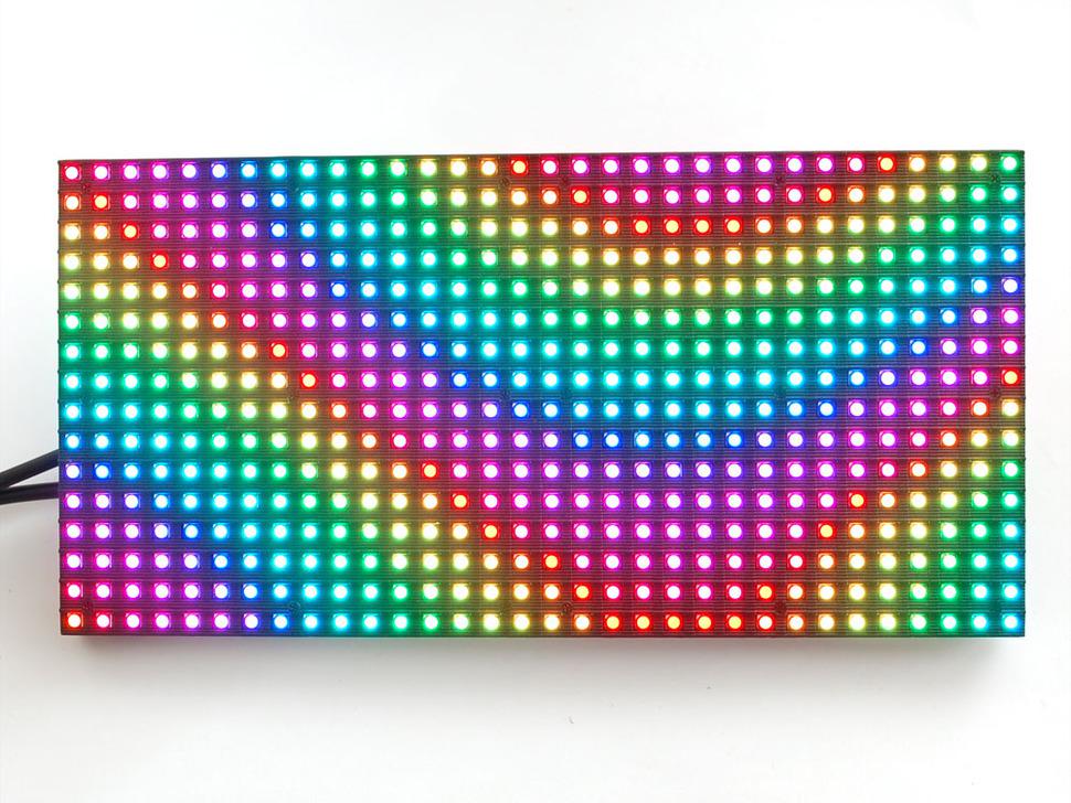
Led Matrix 16x32 RGB

RGB LED matrix.
These displays are ‘chainable’ - connect one output to the next input (at this moment Arduino example code does not support this). It requires a high speed processor and more RAM than the Arduino has!
These panels require 12 digital pins (6 bit data, 6 bit control) and a good 5V supply, up to 2A per panel.
These displays are designed to be driven by FPGAs or other high speed processors: they do not have built in PWM control of any kind. Instead, you’re supposed to redraw the screen over and over to ‘manually’ PWM the whole thing. On a 16 MHz arduino, you can squeeze 12-bit color (4096 colors) with 20% CPU usage but this display would really shine if driven by any FPGA, CPLD, Propeller, XMOS or other high speed multi-core controller. The good news is that the display is pre-white balanced with nice uniformity so if you turn on all the LEDs its not a particularly tinted white.
On an Arduino, you’ll need 12 digital pins, and about 800 bytes of RAM to buffer the 12-bit color image.
Tutorial can be found on learn.adafruit.
WARNING: connector and power cables are no longer included
Categories
-
Accessories
Arduino
ARM
BBC micro:bit
-
Extensions for micro:bit
micro:bit development boards
Power supply for micro:bit
Protection case for micro:bit
Suppliers
Newsletter
Once, twice in month we will send You info about new products, products on sale and news from Arduino and DIY world. Subscribe
Recently added
-
Optocoupler module, 2 channels, PC817


-
16-ch multiplexer module (CD74HC4067)
")
-
LED 8x32 (red) matrix module driven by MAX7219
 matrix module driven by MAX7219")
-
LED 8x32 (green) matrix module driven by MAX7219
 matrix module driven by MAX7219")
-
N-channel IRLB8721PBF MOSFET transistor, 30V, 62A

-
DHT11 module for ESP01

-
Triple Wemos D1 mini proto board

-
Power cable USB A to barrel jack 2.1 x 5.5 mm, 0.5 m

-
AMS1117-33 LDO module (3.3V)
")
-
More products....